What is the Electrical Return Path in a PCB?
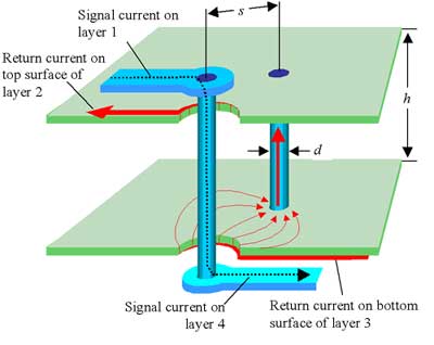
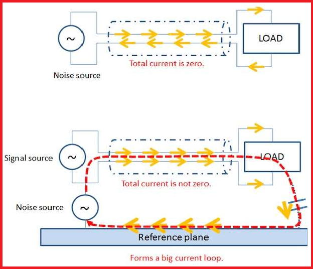
One of the fundamental aspects of any circuit diagram is the return current path or electrical return path. In a circuit diagram and a schematic diagram, the path the current follows to return to the low potential side of a power source should be obvious, but it may not be so obvious in a PCB.
8 PCB Grounding Rules to Live By, EAGLE

How to Design Your PCB Return Current Path

Successful PCB grounding with mixed-signal chips - Part 2: Design to minimize signal-path crosstalk - Engineering Technical - PCBway
How to Handle Current Return Path for Better Signal Integrity

Understanding Return Current Path in PCB – RAM SYSTEMS
The Effects of Non-Ideal Return Paths and Via Resonance on Noise and EMI
How to Handle Current Return Path for Better Signal Integrity

Using Return Paths that Follow Least Impedance to create a better PCB Design
2021 Detail Guide for PCB Ground Plane
Understand the AC and DC Return Path on a High-Performance Mixed-Signal PCB
Ground Plane PCB: A Return Path for Circuit Current and Components

Test Happens - Teledyne LeCroy Blog: Signal Return Paths: A Signal and Power Integrity Tutorial

Using Return Paths that Follow Least Impedance to create a better PCB Design

Return Path Design Rule

Return Current Path - Can Power Planes be used as Return Path?